

Views: 233 Author: Weishi Sheets Publish Time: 2026-10-10 Origin: Site
Content Menu
● G10 vs FR4: Understanding the Material Difference
>> Why Combined G10/FR4 Descriptions Need Clarification
● G10 vs FR4 Comparison for High-Frequency Testing Fixtures
● Why Electrical Insulation Is Not the Same as RF Performance
>> Dielectric Constant Can Affect Fixture Loading
>> Dissipation Factor Matters Where Fields Interact With the Material
● Separate Structural Supports From RF Signal-Path Materials
>> Structural Components Away From Sensitive Fields
>> Components Within Electrically Sensitive Regions
● Machining Accuracy and Finished-Part Consistency
>> Specify Features That Control Measurement Geometry
>> Inspect the Assembled Fixture
>> Include Environmental Conditioning
● A Practical Qualification Workflow for G10 and FR4
>> 1. Define the Application Requirements
>> 2. Request Comparable Material Information
>> 3. Build Geometrically Matched Prototypes
>> 4. Evaluate Response and Reloading Variation
>> 5. Validate Calibration or De-Embedding
>> 6. Freeze the Approved Specification
● Three Practical Selection Scenarios
>> Automated Test Equipment Requiring Flame Retardance
>> A Laboratory Fixture Without a Flame-Retardant Requirement
>> A Fixture With Material Near an RF Launch
● Purchasing Custom G10 and FR4 Fixture Components
● Conclusion: Choose the Material Around the Measurement
>> Is G10 Better Than FR4 for High-Frequency Testing Fixtures?
>> Can FR4 Be Used in an RF Testing Fixture?
>> Does FR4 Always Have the Same Flame Classification?
>> Can Low-Frequency Dielectric Data Be Used for Microwave Design?
>> Will De-Embedding Remove Every Fixture Error?
>> When Should a Specialized RF Laminate Be Considered?
Choosing between G10 vs FR4 for high-frequency testing fixtures requires more than comparing insulation properties. Both materials provide strong, rigid structures for electrical and mechanical applications. However, their suitability depends on flame-retardance requirements, fixture geometry, material consistency, and proximity to the RF signal path.
From a fixture-design perspective, repeatability is the most important starting point. A material must hold the device under test consistently without introducing unacceptable electrical effects. Excellent insulation alone does not guarantee accurate high-frequency measurements.
This guide compares G10 and FR4, explains where each material fits, and provides a practical qualification process for engineers purchasing epoxy fiberglass sheets or custom-machined fixture components.

G10 and FR4 are glass-reinforced epoxy laminates. Manufacturers combine woven fiberglass with epoxy resin and consolidate the layers into rigid sheets under controlled heat and pressure.
Both materials offer a useful combination of mechanical strength, stiffness, and electrical insulation. They are commonly considered for insulating supports, mounting plates, spacers, and other industrial components.
The primary grade distinction is flame retardance. G10 is generally specified without the flame-retardant requirement associated with FR4. FR4 incorporates a flame-retardant resin system.
However, neither designation describes every detail of the supplied product. Resin formulation, glass reinforcement, manufacturing conditions, and sheet construction can differ between manufacturers.
Some suppliers market glass-epoxy products under the combined name "G10/FR4." This description can be convenient for general purchasing, but it leaves important questions unanswered.
For a controlled testing application, confirm:
- The exact supplied grade and product designation.
- Whether flame-retardant performance is required and documented.
- Which technical datasheet applies to the material.
- Whether the finished component remains traceable to the supplied sheet.
A commercial label should never replace an application-specific material specification.
Neither material automatically provides better RF performance. The following comparison establishes a starting point for selection rather than a universal performance ranking.
| Selection Factor | G10 | FR4 | Practical Fixture Consideration |
|---|---|---|---|
| Basic construction | Woven fiberglass and epoxy | Woven fiberglass and flame-retardant epoxy | Both provide rigid insulating structures |
| Flame retardance | Not its defining grade requirement | A defining grade feature | Verify the supplied product's documentation |
| Mechanical characteristics | High strength and stiffness | High strength and stiffness | Compare actual products and finished geometry |
| Electrical insulation | Suitable for many insulating components | Suitable for many insulating components | Breakdown resistance does not establish RF suitability |
| High-frequency dielectric behavior | Requires product-specific evaluation | Requires product-specific evaluation | Compare properties under relevant test conditions |
| Machined-component suitability | Suitable candidate for structural insulation | Suitable candidate where flame retardance is needed | Validate dimensional accuracy and assembly consistency |
| Material selection priority | Application performance and permitted fire behavior | Application performance plus required fire behavior | Avoid selecting by grade name alone |
The most useful comparison is between two identified products manufactured and tested under clearly documented conditions.
A common mistake is assuming that a strong electrical insulator must also be ideal for a high-frequency fixture.
These characteristics address different engineering questions.
Dielectric strength describes resistance to electrical breakdown. Relative permittivity, often called dielectric constant or Dk, describes how a material interacts with an electric field. Dissipation factor, commonly called Df, describes dielectric energy loss.
A fixture can therefore provide adequate insulation while still influencing the measured signal.
When laminate material sits near exposed conductors, connector transitions, or capacitive sensing regions, it can change the local electromagnetic environment.
For FR4, dielectric behavior varies with construction and measurement conditions. Glass reinforcement, resin content, and test method all matter.
Apply the same discipline to G10. Do not assign a presumed dielectric advantage to a sheet simply because its label says G10.
If material interaction affects the measurement, request data for the actual product and validate the finished arrangement.
Dielectric loss becomes important when appreciable electromagnetic field energy interacts with the laminate.
The impact depends on more than the material alone. Thickness, conductor arrangement, geometry, and frequency also influence the result.
Consequently, statements such as "G10 is always lower-loss than FR4" are not a reliable purchasing basis.
Compare candidate materials at relevant frequencies using compatible methods. A value measured at a lower frequency should not be presented as verified microwave performance.
Before choosing a laminate, identify its function in the fixture.
Typical examples include:
- Baseplates.
- Device-support blocks.
- Insulating spacers.
- Probe-support brackets.
- Mounting and alignment components.
For these parts, mechanical stability and consistent positioning may be more important than small differences in dielectric behavior.
Both G10 and FR4 can be reasonable candidates. Flame-performance requirements and finished-part qualification determine which is appropriate.
Material selection becomes more demanding when the laminate supports exposed RF conductors, sits underneath connector launches, or serves as a transmission-line substrate.
Here, dielectric behavior becomes part of the electrical design.
If ordinary glass-epoxy material cannot meet the application's loss or consistency requirements, consider a characterized high-frequency laminate.
A practical design approach is to separate the structural carrier from the RF insert. This allows the mechanical support and signal-path material to be selected independently.
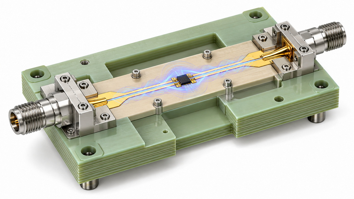
A suitable raw sheet does not automatically produce a suitable fixture.
Machining, assembly, and inspection determine whether the finished component holds the device consistently.
Focus the drawing on features that influence positioning:
- Reference-face flatness.
- Hole locations relative to defined datums.
- Pocket depth.
- Mating-surface alignment.
- Connector and probe positioning.
- Edge quality around thin walls and narrow features.
Avoid applying equally tight tolerances to every dimension without considering function.
Instead, identify which deviations could alter spacing, contact pressure, or alignment. These are the features that deserve the strongest inspection controls.
Inspect the component after machining, cleaning, and installation.
Check whether fasteners, locating features, and mating surfaces maintain the intended geometry. A dimensionally acceptable part can still produce an inconsistent assembly if its interfaces allow movement.
For repeated testing, assess the complete fixture rather than relying only on a raw-material certificate.
Temperature and moisture conditions should be defined before comparing materials.
Do not assume that a stable-looking glass-epoxy part will behave identically under every environment.
Condition candidate fixtures consistently, then evaluate whether mechanical alignment or electrical response changes enough to affect the measurement.
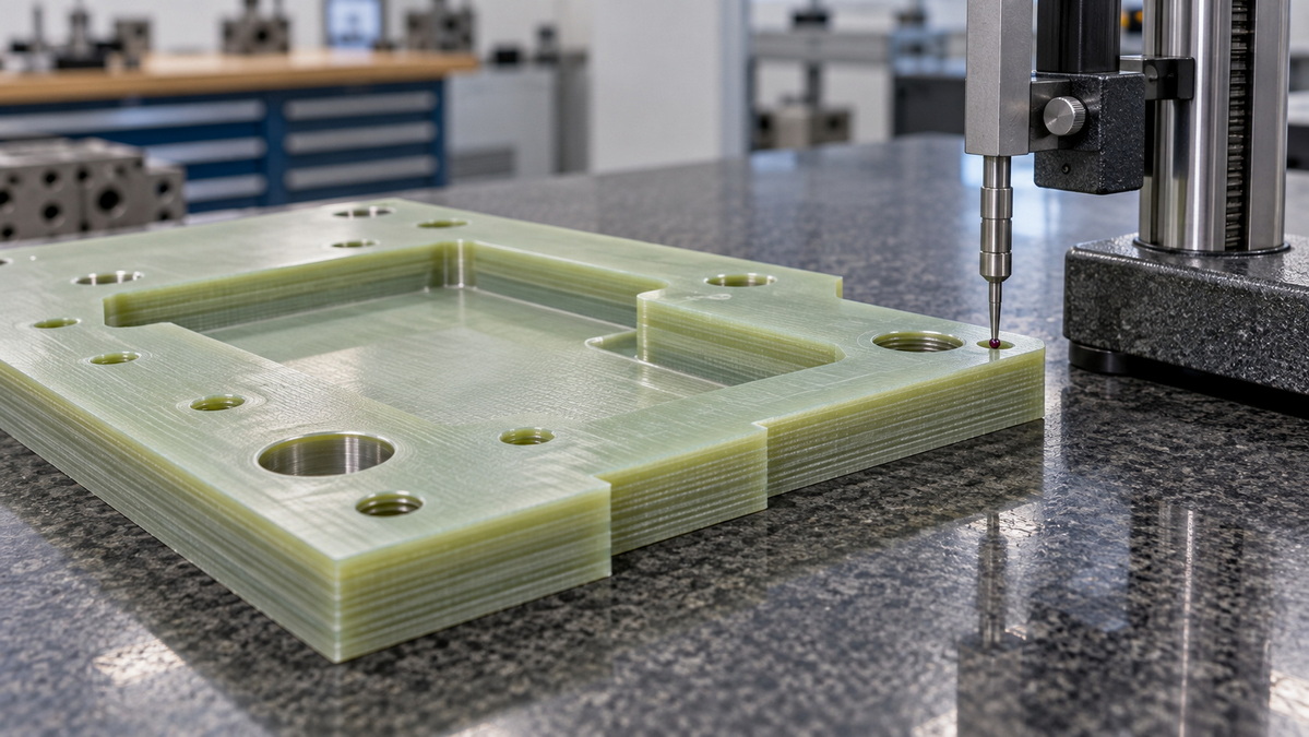
The following process helps separate material effects from assembly effects.
Record the operating frequency range, device interface, environmental conditions, and applicable flame-performance requirements.
Also define acceptable measurement variation and the maximum fixture contribution that the application can tolerate.
Without these criteria, "better performance" remains subjective.
Where dielectric interaction matters, request product-specific information covering:
- Measurement frequency.
- Test method.
- Sample thickness and orientation.
- Temperature and moisture conditioning.
- Whether the reported values are typical or guaranteed.
Do not compare unrelated datasheet values as though they were measured under identical conditions.
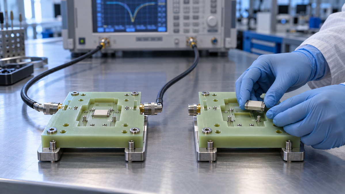
Keep the connector arrangement, fasteners, cable routing, mounting conditions, and device location unchanged.
If several variables change simultaneously, the test cannot isolate the laminate's contribution.
Matched prototypes provide a more useful comparison than unrelated fixtures made from different materials.
Characterize the relevant electrical path.
Then repeatedly remove and reinstall the same reference device. Evaluate both the average response and the variation between installations.
A fixture that delivers one favorable measurement but inconsistent subsequent results may be unsuitable for production testing.
If the fixture introduces meaningful electrical effects, characterize those effects and validate the correction method.
De-embedding mathematically removes a characterized fixture response to move the measurement reference plane toward the device interface.
However, it should not be treated as a cure for unstable assembly. A correction based on one fixture state may not represent another state accurately.
Document the qualified material, drawing revision, machining requirements, conditioning procedure, and acceptance tests.
Require review before changing the supplied product, laminate construction, or manufacturing arrangement.
This step protects the connection between the validated prototype and subsequent production components.
The following examples illustrate selection logic. They are hypothetical engineering scenarios, not reported customer results.
The laminate supports a device nest outside the main RF path, and the equipment specification requires documented flame-retardant performance.
FR4 is the logical starting candidate, provided the supplied product meets the requirement.
Mechanical inspection and repeated loading tests remain necessary.
The primary needs are rigid insulation, accurate machining, and consistent device positioning.
G10 is a reasonable candidate.
However, selecting it because it is assumed to be universally superior at high frequencies would be unsupported. Validate the actual fixture.
An insulating component sits close to an exposed conductor, and the response changes when its position changes.
Start by assessing geometry and material-field interaction.
Moving the support, modifying the arrangement, or using a qualified RF insert may be more effective than switching between G10 and FR4 alone.
A complete enquiry helps the manufacturer evaluate requirements and reduces avoidable assumptions.
Provide:
1. The component drawing and revision.
2. The intended material grade.
3. The operating frequency range.
4. Critical dimensions and datums.
5. Flame-performance documentation requirements.
6. Environmental conditions.
7. Inspection and traceability expectations.
A quotation based only on thickness, color, and overall dimensions does not establish suitability for high-frequency testing.
Guangdong Weishi New Materials Co., Ltd. develops, produces, and supplies epoxy fiberglass insulation materials, including FR4 and G10/G11, with custom-processing capabilities.
Product-specific RF performance, certifications, and acceptance criteria should be confirmed through relevant documentation and sample qualification.
The G10 vs FR4 decision is best understood as a fixture-engineering question.
Choose FR4 when documented flame-retardant performance is required. Consider G10 when application requirements permit it and the selected product meets the mechanical and electrical needs.
For electrically sensitive regions, qualify the actual laminate at relevant frequencies. For structural components, prioritize geometry, assembly stability, and consistent positioning.
Send Guangdong Weishi New Materials Co., Ltd. your fixture drawing, operating frequency range, and material requirements to discuss suitable epoxy fiberglass sheets and custom-machined components. Request supporting documentation and approve qualified samples before moving into production.
Not automatically. Material formulation, fixture geometry, operating frequency, and proximity to the signal path determine suitability. Compare identified products under matched conditions.
Yes. FR4 can provide structural electrical insulation. When it interacts with the RF signal path, its dielectric behavior must be included in design and validation.
Do not infer an exact classification from the grade name alone. Verify documentation for the supplied product and the relevant conditions.
Such data should not be treated as verified microwave performance. Request suitable characterization for the intended operating band.
No. It corrects a characterized electrical contribution. It does not automatically resolve changing geometry, inconsistent contacts, or unstable assembly.
Consider one when ordinary glass-epoxy material cannot satisfy signal-path loss, dielectric consistency, or modeling requirements. Validate the completed fixture after material selection.
1. Curbell Plastics — "G10/FR-4 Glass Epoxy." Material composition, structural properties, and electrical insulation applications. [curbellplastics]
2. Piedmont Plastics — "G10 vs. FR4: Which Fiberglass Laminate Should You Choose?" Grade distinctions and flame-retardance considerations. [piedmontplastics]
3. Boedeker Plastics — "Glass Composites." Glass-epoxy material descriptions and insulating structural applications. [boedeker]
4. Keysight — "Basics of Measuring the Dielectric Properties of Materials." Dielectric-property definitions, measurement techniques, and test-condition considerations. [cmc]
5. Keysight — "16453A Dielectric Material Test Fixture." Parallel-plate characterization, frequency limitations, and sample requirements. [keysight]
6. Keysight — "How to De-Embed High-Speed Test Fixtures." Fixture characterization, reference-plane correction, and de-embedding considerations. [keysight]
7. Altium — "FR4 Dielectric Constant and Material Properties." FR4 dielectric variability and construction-related considerations. [resources.altium]
8. Rogers Corporation — "High Frequency Electronics Product Selector Guide." Selection considerations for dedicated high-frequency laminates. [rogerscorp]
9. Rogers Corporation — "Circuit Materials and High-Frequency Losses of PCBs." Relationships between material characteristics, construction, and high-frequency loss. [rogerscorp]


